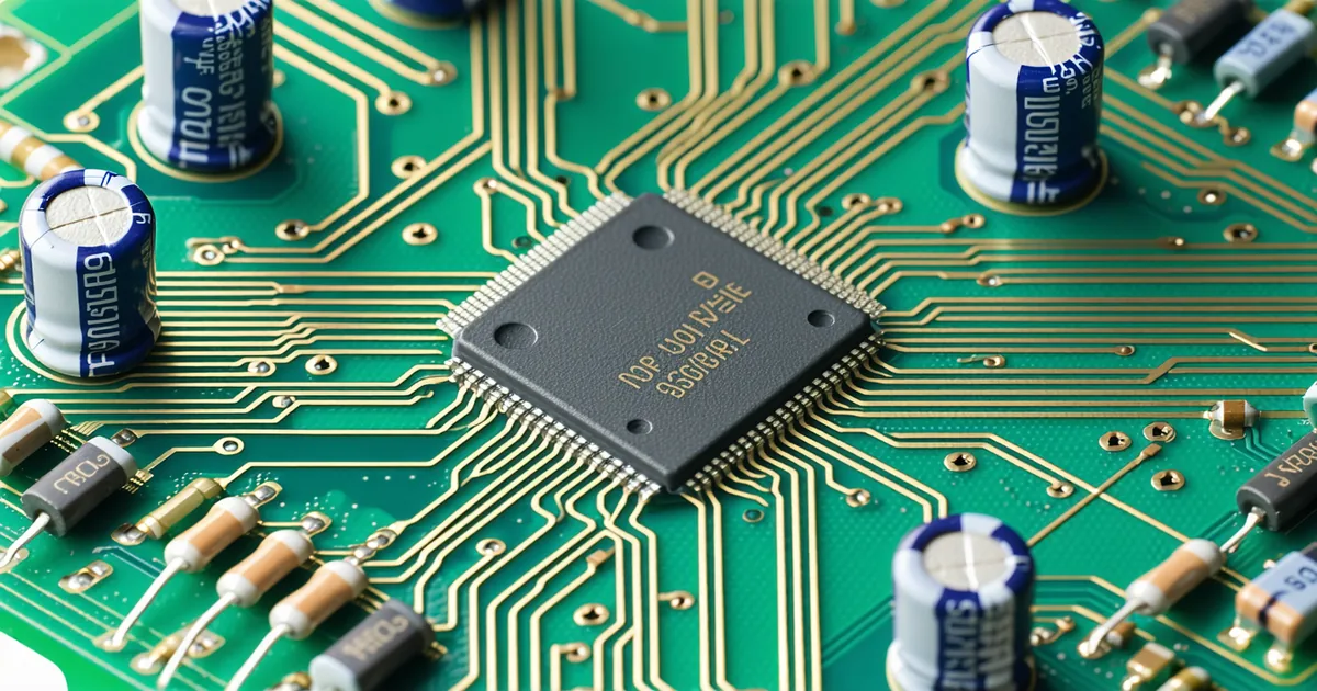
Integrating a discrete HSM die onto a host PCB is a different engineering problem from integrating a general-purpose microcontroller or FPGA. The security properties of the die depend on the PCB implementation — a poorly-designed power supply domain or an incorrectly-terminated debug interface can undermine security guarantees that the silicon itself provides. This guide covers the PCB-level decisions that matter for a functioning, secure integration: power decoupling, tamper mesh connectivity, thermal management for BGA packages, JTAG security, secure boot fusing, and reset glitch countermeasures.
Power Supply Architecture and Decoupling
A security IC typically requires multiple supply domains: a core logic supply (commonly 1.0V–1.2V for 28 nm), an I/O supply (1.8V or 3.3V for SPI/PCIe interfaces), and a battery backup domain for the tamper mesh monitor (typically 1.5V–3.6V from an external coin cell). Each domain must be decoupled independently.
Core logic decoupling follows standard practice for high-frequency CMOS: 100 nF and 10 nF ceramic capacitors in X5R or X7R dielectric, placed within 0.5 mm of each power pin, with a 10 μF bulk capacitor per power domain. For a BGA package, the decoupling capacitors should be placed in the via escape region on the reverse side of the PCB, as close to the BGA balls as the via capture pad routing allows. Capacitors placed more than 2 cm from the package are dominated by PCB trace inductance at frequencies above ~100 MHz and contribute negligible decoupling at the die's switching frequencies.
The battery backup domain deserves special attention. The backup supply must be isolated from the main supply by a diode (Schottky preferred for low forward voltage) or a PMOS pass transistor, such that removing the main supply does not discharge the battery through the main supply regulator's internal discharge path. The isolation circuit must be characterized for reverse current leakage at the minimum battery voltage (typically 2.0V for a depleted Li coin cell) to ensure the backup supply does not drain through the isolation device into the main supply node when main power is removed.
Power sequencing matters for security ICs because the tamper detection circuit must be operational before any key material is accessible. If the core supply ramps before the tamper mesh monitor supply, there is a window at power-on during which keys are potentially accessible without tamper coverage. The recommended sequence is: battery backup domain always live; main core supply and tamper mesh monitor supply rise together (or mesh monitor first); I/O supply rises last after the core is stable. An enable signal from the security controller to the I/O supply LDO, driven only after the tamper detection circuit signals its operational status, implements this sequencing in hardware.
Tamper Mesh PCB Connectivity
An active tamper mesh requires the PCB to route challenge and sense signals between the security IC and the mesh conductors. If the tamper mesh is entirely on-die (as in a monolithic HSM ASIC with on-chip mesh over all sensitive logic), the PCB only needs to provide the battery backup supply and no additional mesh routing. If the tamper mesh extends off-chip (for example, covering the package and surrounding BGA region), the PCB routing becomes part of the security boundary.
For an off-die tamper mesh, the PCB traces carrying the PRBS challenge and sense signals must themselves be protected. An attacker who can probe these traces — before they enter the IC — may be able to observe the PRBS and reconstruct the challenge for a bypass attack. The standard approach is to route mesh traces on inner PCB layers with copper pour flood on the adjacent layers, creating a conductive enclosure that cannot be probed without cutting the flood — which itself acts as an additional passive tamper indicator. The PCB layout tool must be set to avoid automatic routing of any other signal in the inner layers assigned to tamper mesh signals.
Connector pinouts for the battery backup domain on serviceable modules (those where the battery is replaceable) must be designed so that the battery can be replaced without the mesh monitor power rail dropping below its minimum operating voltage during the swap. A capacitor hold-up buffer on the monitor supply, sized for the expected battery-swap time (typically 5–10 seconds with the system powered), prevents false tamper events during battery replacement.
BGA Package Thermal Management
A dedicated security ASIC in a BGA package has thermal requirements that differ from a server CPU — the absolute power dissipation is lower (typically 1–3 W for an HSM die), but the temperature operating window is often broader for industrial or defense applications (-40°C to +85°C extended, or -55°C to +125°C military grade). Thermal derating of BGA solder joints at temperature extremes is a reliability concern: the coefficient of thermal expansion (CTE) mismatch between the die substrate and the PCB laminate causes solder joint fatigue under temperature cycling.
For a 15 mm × 15 mm BGA with 0.8 mm ball pitch on FR4 PCB, JEDEC-standard thermal cycling qualification (per JESD22-A104) to -40°C/+125°C for 500 cycles is a reasonable qualification requirement for industrial-grade deployment. For defense programs specifying MIL-SPEC thermal cycling to 1000+ cycles, the PCB laminate material selection (low-CTE polyimide-based laminate rather than standard FR4), corner ball underfill dispensing, and solder alloy selection (SAC305 is the standard Pb-free choice; SnPb 63/37 remains in use for military waiver programs) all affect fatigue life prediction.
Thermal vias through the PCB below the BGA thermal pad conduct heat to the ground plane and ambient. For a 2 W dissipation with no heatsink, the junction temperature rise above ambient is dominated by the package-to-board thermal resistance (typically 10–20°C/W for a molded BGA package). A fully-populated via field under the thermal pad (0.3 mm drill, 0.6 mm pitch, filled and plated) brings the board-side thermal resistance to approximately 3–5°C/W, keeping junction temperature within spec at 85°C ambient.
JTAG Security and Debug Interface Lockout
JTAG is the most common vector for unintended post-deployment key access. A security IC that retains functional JTAG access in production silicon allows an attacker with physical access and a JTAG probe to scan device registers, including — in insufficiently hardened implementations — key storage registers. The correct approach is hardware JTAG lockout via security fuse.
Most security ASICs provide a one-time programmable fuse bit that disables the JTAG TAP controller, or at minimum restricts it to a boundary-scan-only mode that cannot access internal registers. This fuse must be blown during manufacturing or initial provisioning — not during field deployment — because any window where JTAG is enabled in a shipped device is a window for a supply-chain attacker. The hardware JTAG lockout fuse should be blown as part of the same provisioning sequence that performs initial PUF enrollment.
On the PCB, JTAG pins should be connected to test pads that are only accessible with deliberate physical access (internal PCB layer pads, or pads covered by conformal coating). Bringing JTAG signals to an exposed header connector on a production assembly is a hardware security failure regardless of software-level JTAG disable, because the connector itself can be used to apply glitch attacks on the supply or reset pins adjacent to it.
Reset Glitch Attack Countermeasures
A reset glitch attack applies a brief voltage pulse to the reset pin at a precisely-timed moment during boot, attempting to cause the processor to skip security-critical initialization code (such as the JTAG disable fuse check or the tamper detection initialization). If successful, the attacker may bring the device to a state where debug access is functional even though the JTAG disable fuse is blown.
PCB-level countermeasures: the reset pin should be driven through a resistor-capacitor filter (100 Ω series, 100 nF to ground) that sets a minimum reset pulse width of approximately 10 μs, filtering out sub-microsecond glitch pulses. The reset pin should not be exposed at a test connector in production units. A voltage supervisor (brown-out detector) with an adjustable threshold should monitor the core supply and assert reset if the supply drops below the minimum operating voltage — this prevents partial power-down states that can cause erratic behavior in security-critical initialization code.
We're not saying PCB-level countermeasures alone are sufficient for defense against a well-resourced attacker with unlimited physical access time. We're saying that correct PCB design eliminates the opportunistic attack surface — the class of attacks that can be performed quickly with commodity tools — and significantly raises the cost and expertise required for more sophisticated physical attacks. Defense in depth at the PCB layer complements the silicon-level tamper mesh and PUF design, not substitutes for it. Every integration that omits the decoupling, JTAG lockout, or reset glitch countermeasures listed here is eroding the security margin that the silicon provides.